Tadalafil zeigt eine konstante Resorption im Gastrointestinaltrakt, mit maximalen Plasmaspiegeln nach rund zwei Stunden. Der Wirkstoff verteilt sich gut im Gewebe und weist eine hohe Plasmaproteinbindung auf. Seine lange Halbwertszeit erlaubt eine verlängerte Wirkphase. Der Metabolismus erfolgt über das hepatische Enzymsystem CYP3A4, mit der Bildung inaktiver Metaboliten. Exkretion geschieht primär über den Stuhl. Die Häufigkeit von Nebenwirkungen steigt mit der Dosis, wobei vor allem vasodilatatorische Effekte dominieren. Ein gängiger Bezugspunkt in pharmakologischen Analysen ist cialis ohne rezept, das mit dieser Wirkstoffklasse assoziiert ist.
Microsoft word - manualmain.doc
VLS-AIM INTERFACE MODULE
MANUAL INTRODUCTION
The information is this manual is intended as an installation guide for the Videx intercom to SmartDisc/SmartTel digital video transmission system. This manual should be read carefully before the installation commences. Any damage caused to the equipment due to faulty installations where the information in this manual has not been followed is not the responsibility of Vista. SYSTEM INTRODUCTION
The VLS-AIM module has been designed to interface a standard Videx door panel with the Vista SmartDisc/SmartTel Digtial video transmission system to allow a call to be made from the Videx door panel. Both duplex speech and video are supported by the system and a facility to release a lock is also available. For more information please consult the SmartDisc/SmartTel manual. SYSTEM COMPONENTS
The VLS-AIM will interface with any of the following Videx door amplifiers (For convenience they are shown with camera and back box as sets):- Description Modules required Module frame required
for gold or no suffix for gunmetal grey)
4000 Series Flush colour video door panel
Art.4851 (Suffix /C for chrome, /G for gold or no suffix for gunmetal grey)
800 Series surface colour video door panel Art.837-1, Art.830C
800 Series flush colour video door panel Art.837-1,
for gold or no suffix for gunmetal grey)
Art.4851 (Suffix /C for chrome, /G for gold or no suffix for gunmetal grey)
800 Series surface mono video door panel
800 Series flush mono video door panel Art.837-1,
for gold or no suffix for gunmetal grey)
4000 Series Flush colour video door panel
Art.4852 (Suffix /C for chrome, /G for gold or no suffix for gunmetal grey)
for gold or no suffix for gunmetal grey)
4000 Series Flush colour video door panel
for gold or no suffix for gunmetal grey)
for gold or no suffix for gunmetal grey)
4000 Series Flush colour video door panel
for gold or no suffix for gunmetal grey)
DOOR PANELS The door panel connections are as follows:- Connection Function
Speech volume adjustments are carried out at the door panel using a small trimmer driver.
VLS-AIM The VLS-AIM interface connections are as follows:- Connections Function
Centre core of video coax cable from door panel
Screen of video coax cable from door panel
Connected to line in on the SmartDisc/SmartTel
Connected to Line out on the SmartDisc/SmartTel
Connected to relay 1 on the Smart/Disc/SmartTel (Activate video and speech)
Connected to alarm input on SmartDisc/SmartTel (Call activation)
Centre core of video coax to SmartDisc/SmartTel
Screen of video coax to SmartDisc/SmartTel
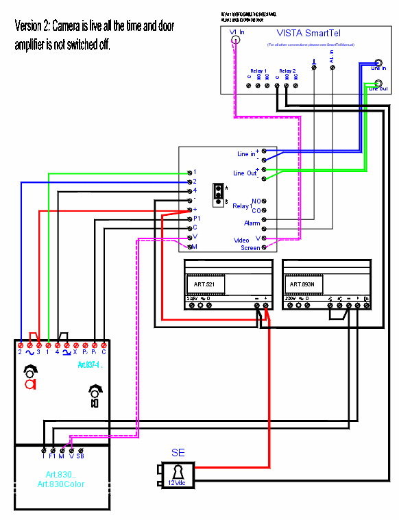
The speech and video from the door panel can either be live all the time or only switched on when required. Note: We recommend only having the video and speech switched on
PAGE 2 of 6 VLS-AIM TECHNICAL MANUAL
when required to reduce current consumption and avoid the amplifier being live all the time. JP1 on the VLS-AIM PCB selects this option as shown below:-
SPEECH AND VIDEO LIVE All the time Only during a call
AUDIO SYSTEM POWER SUPPLY
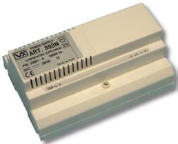
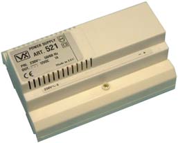
The Art521 is a 12Vdc power supply with a 800mA continuous or 1A surge output. CONNECTIONS Terminal Function +12 VIDEO POWER SUPPLY Art. 893N 20Vdc 800mA continuous 1A surge PSU. This power supply only has an output when either a 0V is applied to –C or when a voltage is applied to +C. At all other times the + output is switched off.
Connection Function 230V~ 0
Switched 20Vdc output (Triggered by –C or +C)
+ volts trigger input (From 8V up to 30V)
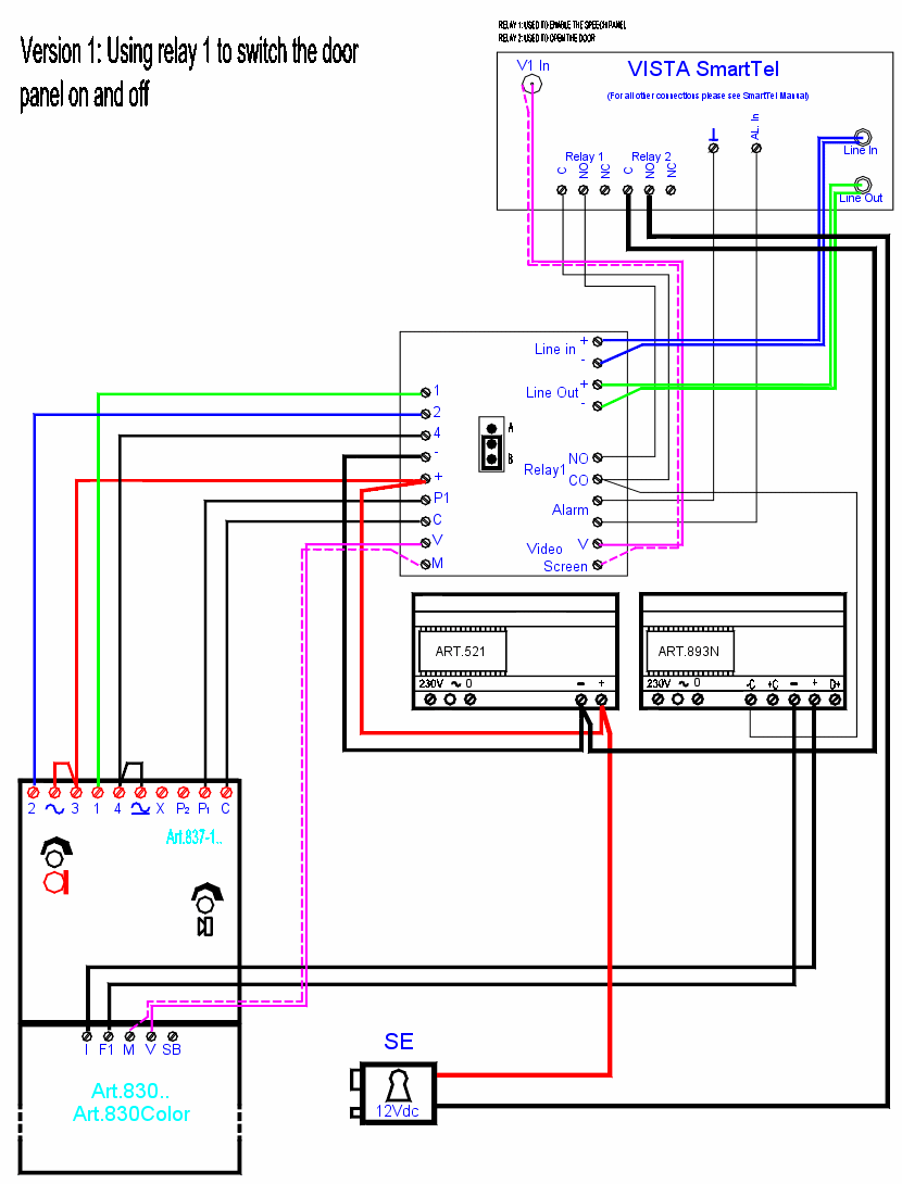
SYSTEM OPERATION When a call is placed from the door panel a signal is sent to the SmartDisc/SmartTel alarm input. The SmartDisc/SmartTel operator must then activate relay 1 to open the speech and video paths to the door panel. The SmartDisc/SmartTel operator can then activate relay 2 to release the door if required. Please consult the SmartDisc/SmartTel manual for more information. INSTALLATION The wiring diagrams towards the back of this manual should be followed carefully. Heavy duty conductors on wiring diagrams are shown heavily outlined, These wires should be doubled up. PAGE 3 of 6 VLS-AIM TECHNICAL MANUAL
- Check that all components are free from damage before installing (Do not proceed with
- Keep all packaging away from children. - Do not obstruct the ventilation openings or slots on any of the devices. - All connections to mains voltages must be made to the current national standards (IEE
- Install an appropriate fused spur or isolation switch to isolate the mains. - Isolate the mains before carrying out any maintenance work on the system. - All intercom and access control cables must be routed separately from the mains. Lock release protection : A diode must be fitted across the terminals on the lock release to suppress back EMF voltages. The diagram below shows the polarity of the diode when fitted to the release. LOCK RELEASE
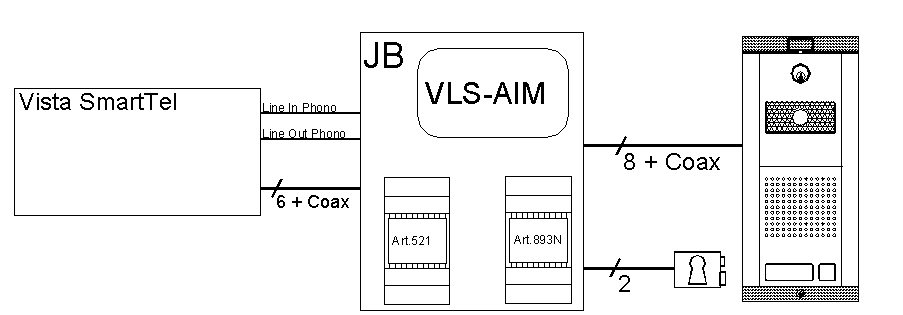
Cable size and type : When running cables for any intercom system, these cables must be installed separately from the mains cables. All multi pair cables should be to CW1308 specification. (0.5mm twisted pair telephone cable). Max resistance = 10 Ohm. Lock release wires should be doubled up. Max resistance = 3 Ohm The cables sizes above can be used for distances up to 50m. On distances above 50m the cable sizes should be increased to keep the overall resistance of the cable below the RESISTANCES indicated above. SYSTEM BLOCK DIAGRAM
Minimum cable requirements shown PAGE 4 of 6 VLS-AIM TECHNICAL MANUAL PAGE 5 of 6 VLS-AIM TECHNICAL MANUAL PAGE 6 of 6 VLS-AIM TECHNICAL MANUAL
Personal Kit List Consumables ☐ Gloves (need a winter & summer pair) Bike Spares List ☐ Tyres (spare + wet/dry weather change) Ride Hardware Nutrition ☐ Pre-race & recovery shake (3 servings per day)☐ Sports drink (plan at least 750ml per hour) First Aid ☐ Glutamine (1 teaspoon per day - post race)☐ an electrolyte formula containing magnesium, calc
MATERIAL SAFETY DATA SHEET (Intermediate) Product: 1,1'- METHYLENEBIS (ISOCYANATOBENZENE) 26447-40-5 This product contains the following toxic chemical or chemicals subject to the reporting requirements of Section 313 of Title III of the Emergency Planning and Community Right-To-Know Act of 1986 and 40 CFR Part 372: BENZOYL CHLORIDE 2. PHYSICAL DATA BOILING POINT: N/D - Not Determined N/A - N


 VLS-AIM INTERFACE MODULE


 when required to reduce current consumption and avoid the amplifier being live all the time. JP1 on the VLS-AIM PCB selects this option as shown below:-
SPEECH AND VIDEO LIVE
when required to reduce current consumption and avoid the amplifier being live all the time. JP1 on the VLS-AIM PCB selects this option as shown below:-
SPEECH AND VIDEO LIVE


 - Check that all components are free from damage before installing (Do not proceed with
- Keep all packaging away from children. - Do not obstruct the ventilation openings or slots on any of the devices. - All connections to mains voltages must be made to the current national standards (IEE
- Install an appropriate fused spur or isolation switch to isolate the mains.
- Check that all components are free from damage before installing (Do not proceed with
- Keep all packaging away from children. - Do not obstruct the ventilation openings or slots on any of the devices. - All connections to mains voltages must be made to the current national standards (IEE
- Install an appropriate fused spur or isolation switch to isolate the mains. 


 PAGE 5 of 6


 PAGE 6 of 6